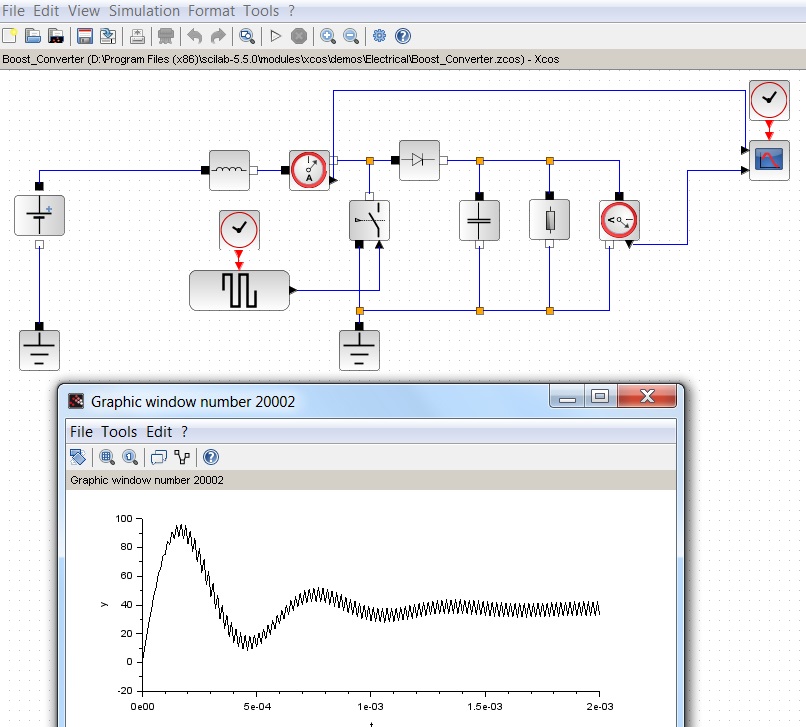

Referring to the analysis of Part (b) of this activity, we experimentally collected frequency response data from the boost converter circuit. Furthermore, this activity demonstrates how embedded controllers are oftenĭesigned and implemented in practice using modern design and code generation tools. The purpose of this activity is to demonstrate how to design a controller using frequency response techniques based on anĮmpirically derived, and imperfect, plant model. (Rload) resistance of the load resistor (Req) equivalent series resistance (ESR) of the inductor (L) inductance of the inductor (C) capacitance of capacitor (ei) input voltage (from the battery) (eo) output voltage This control logic to the microprocessor on the Arduino board.Ī schematic of the boost circuit we will control in this section is shown below including a list of the variables we will Will be specified within Simulink and initially the controller will run on-board the host computer. The Arduino board will also communicate the recorded data to Simulink for visualization and analysis. Of the circuit via one of the board's Analog Inputs and for controlling the level of the output voltage via one of the board's Digital Outputs. In this activity, the Arduino board will be used for measuring the output Response approach to design the feedback controller. input voltage source changes, load changes, etc.). Such a control system is necessary if it is desired to change the output voltage setpoint, or if In this part of the activity, we will implement a control system in order to control the output voltage The frequency response behavior of a boost converter is studied in Part (b) of this activity.

Details regarding the principle of operation of a boost converter can beįound in Part (a) of this activity. a battery) and outputĪn (approximately) constant higher output voltage. The purpose of a boost converter is to take the voltage supplied by a constant voltage source (e.g. The system we will be employing in this activity is a type of DC/DC converter called a Boost (Step-Up) Converter. Electronic components (inductor, resistor, capacitor).Also explore hardware-in-the-loop (HIL) testing of the microcontroller using a Speedgoat ® real-time target machine. See how to use control algorithms to generate embedded code optimized for implementing on a Texas Instruments™ C2000™ microcontroller. MathWorks engineers show how to use Simulink and Simscape Electrical to develop, simulate, and implement a controller that maintains desired output voltage in the presence of input voltage variations and load changes to achieve a fast and stable response. Get a demonstration of SEPIC circuit topology and how to model and simulate a DC-DC converter that powers a strip of LEDs. Learn how to model and simulate a DC-DC converter in Simulink ® and Simscape Electrical™.


 0 kommentar(er)
